Murata 1SC & Quectel BG770A-SN Setup Guide
This guide walks through the setup and configuration process for using the Murata 1SC or Quectel BG770A-SN module with a planNT1-provisioned Soracom IoT SIM card for NTN satellite communication via the Skylo network.
Requirements
-
Murata 1SC or Quectel BG770A-SN-based evaluation kit (EVK) or module. Murata Type 1SC-NTN Evaluation Kits are available from the Soracom store:
- Murata Type 1SC-NTN Evaluation Kit (with included plan01s SIM)
- Murata Type 1SC-NTN Evaluation Kit (with included plan-US SIM)
This guide is not suitable for the setup of the Soracom iSIM Evaluation Kit (EVK) based on Murata Type 1SC, which is a cellular evaluation kit without satellite connectivity.
- Soracom IoT SIM provisioned with planNT1 and the correct IMSI enabled. This process is described in our Air for Satellite Configuration documentation.
- Serial terminal software (e.g., TeraTerm, PuTTY, minicom)
- USB cable for EVK connection
- Internet-connected PC
Hardware Setup
- Insert your planNT1-provisioned SIM card into the device.
- Connect the EVK to your PC using the USB cable.
-
Determine the serial port assigned to the EVK:
-
Windows:
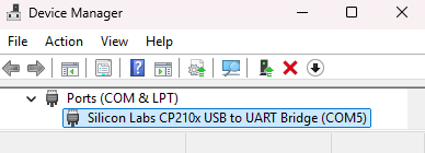
- Open Device Manager by pressing Win+X, then selecting Device Manager.
-
Expand Ports (COM & LPT) and note the COM port number assigned to your device (COM3). If multiple devices are connected, the easiest way to identify the correct port is to open Device Manager first, then plug in your EVK and watch for the newly listed entry.
- Linux:
- Run
dmesg | grep ttyafter plugging in the device to see which/dev/ttyUSB*or/dev/ttyACM*port the EVK is assigned. - Alternatively, use
ls /dev/tty*before and after plugging in to spot the new device.
- Run
-
-
Launch a serial terminal and connect to the EVK's COM port:
In this guide, the PuTTY and minicom programs are used to create a serial connection with a Windows or Linux PC, respectively; however, other serial terminals can be used as well.
-
Windows (PuTTY):
- Download and install PuTTY.
- Select Serial as the connection type.
-
Enter the COM port number and set the baud rate as specified by your EVK (typically
115200).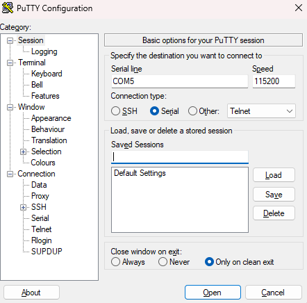
- Click Open to start the session.
-
Linux (bash):
-
Install
minicomwith your distribution's package manager:sudo apt install minicom -
Check which
ttyport the device is using:dmesg | grep tty - Use
minicomto connect to the correctttyport at the baud rate specified by your EVK (typically115200):sudo minicom -D /dev/ttyUSB0 -b 115200
-
-
Initial Configuration
After opening a terminal connection, configure the module with the following AT commands:
-
Set the module to offline mode:
AT+CFUN=0 -
Set the APN for Soracom connectivity:
AT%PDNSET=1,"soracom.io","IP" -
Select the RAT image for NB-IoT NTN operation:
AT%RATIMGSEL=2 -
Activate NB-IoT in NTN mode:
AT%RATACT="NBNTN",1 -
Set the frequency band for your region: Use Band 256 for Europe, Band 255 for the UK, Oceania, and Brazil, or Band 23 for the US and Canada.
AT%SETCFG="BAND","256" -
Set the estimated GPS location (latitude, longitude, altitude in meters):
AT%NTNCFG="pos","stat","51.5396","-0.1597","20" -
(Optional) Configure the use of internal GNSS:
- Enable use of internal GNSS:
AT%SETACFG="ntn.conf.gnss_in_use","ignss" - Enable the local GNSS service:
AT%SETACFG="locsrv.operation.locsrv_enable","true" - Activate internal GNSS:
AT%IGNSSACT=1 - (Optional) Request a single GNSS fix:
AT%IGNSSINFO="FIX"
Requesting a GNSS fix is not required for NTN operation. When internal GNSS is enabled, the module uses the GNSS position internally to set up the NTN link. Request a fix only if your application needs the device position. To be notified automatically each time a fix is acquired, see
AT%IGNSSEV="FIX",1in the Debugging Notifications table below. - Enable use of internal GNSS:
-
Enable the modem to connect to the Skylo network:
AT+CFUN=1 -
Enable unsolicited result codes for network registration:
AT+CEREG=2 -
Ping the Soracom ping server:
AT%PINGCMD=0,"100.127.100.127",1,50,30Sending pings via satellite is not as reliable as general cellular connectivity due to the high latency. Packets may be lost either during transmission or reception. Expect that pings may fail.
Test Data Uplink Sequence
Follow these steps to test UDP data uplink using AT commands.
-
Add your planNT1-provisioned IoT SIM to a group configured to use Unified Endpoint and Soracom Harvest Data.
-
Allocate a UDP socket:
AT%SOCKETCMD="ALLOCATE",1,"UDP","OPEN","100.127.69.42",23080,0The IP address of Soracom Unified Endpoint is subject to change. If the IP address above does not work, query the DNS for
unified.soracom.iousing a device connected to the Soracom network.The URL
unified.soracom.iomay also be used directly in theAT%SOCKETCMD, but may fail resolution due to the long latency times that can be expected with satellite communications. -
Activate the socket:
AT%SOCKETCMD="ACTIVATE",1 -
Send
Hello, world!as hex:AT%SOCKETDATA="SEND",1,13,"48656C6C6F2C20776F726C6421" -
Check the response:
- If data is received successfully, the module will return the following reply to indicate arriving data:
%SOCKETEV:1,1 - Read the arriving data:
AT%SOCKETDATA="RECEIVE",1,50 - Expected response:
%SOCKETDATA:1,3,0,"323031","100.127.69.42",23080This corresponds to ASCII
201, meaning success.
- If data is received successfully, the module will return the following reply to indicate arriving data:
- Close the socket:
AT%SOCKETCMD="DELETE",1
Power Saving Modes
Both PSM (Power Saving Mode) and eDRX (extended Discontinuous Reception) are available for power optimization. The configuration commands are identical across all supported module types.
eDRX Configuration
eDRX allows the device to sleep for extended periods while remaining registered to the network.
Parameters:
- eDRX cycle length: 10.24 seconds to 2.9127 hours (binary
0001to1111). - Paging Time Window: 10.24 seconds, fixed (binary
0011). - Paging sequence: 1 paging event every 30 seconds (packets discarded after >90 seconds).
Example: Configure eDRX with a 20.48 second cycle:
AT+CEDRXS=2,5,"0010"PSM Configuration
PSM provides deeper power savings by allowing the device to enter a sleep state where it's unreachable by the network.
Timing Parameters:
- RRC Connection Release (transition to idle): 80 seconds.
- PSM Active Timer (T3324): 0 seconds to 3.1 hours (binary
00000000to01011111). (Setting to 0 bypasses idle mode and transitions directly to PSM.) - Extended TAU Timer (T3412): Maximum 24 hours (binary maximum
00111000).
Example: Configure PSM with T3412 (periodic TAU) = 12 hours and T3324 (active timer) = 2 minutes:
AT+CPSMS=1,,,00101100,00100010For assistance with AT+CPSMS command generation, use Soracom's online PSM calculation tool.
Troubleshooting
General troubleshooting steps for Air for Satellite connections can be found in our satellite troubleshooting documentation.
Debugging Notifications
The following optional commands can be used to enable notifications for debugging purposes:
| Command | Description |
|---|---|
AT%NOTIFYEV="SIB31",1 |
Enable notifications when satellite system information (SIB31) is received. |
AT%NTNEV="TA",1 |
Enable TA (Timing Advance) debug event logging. |
AT%NOTIFYEV="RRCSTATE",1 |
Enable RRC state change notifications (e.g., connected, idle). |
AT+CEREG=2 |
Enable URC for network registration status. |
AT%IGNSSEV="FIX",1 |
Enable notifications when a GPS fix is acquired. |
Response Codes
You can monitor for the following response codes during the connection process to confirm network connection:
| Response Code | Meaning |
|---|---|
%NOTIFYEV: "SIB31" |
Satellite detected |
%NOTIFYEV:"RRCSTATE",1 |
RRC connected state |
+CEREG: 5,"0FBA",... |
Registered (roaming) |