Sony Spresense with LTE Extension Board Setup Guide
In this guide, we will set up and configure a cellular connection for the Sony Spresense with LTE Extension Board in order to send data to the Soracom platform.
Requirements
To follow along with this guide, you will need the following:
- Computer with Internet access
- Refer to the Sony Spresense documentation for a list of supported operating systems
- Soracom account
- Soracom IoT SIM card
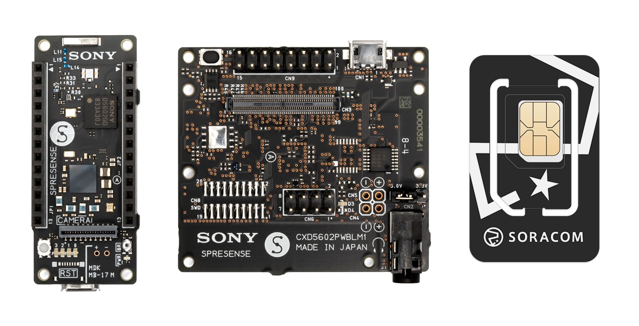
- Sony Spresense Main Board
- Sony Spresense LTE Extension Board
- Micro-USB cable capable of connecting the Spresense Main Board to your computer
In order for the LTE extension board to connect to a cellular network, you will need to be located in an area where LTE Cat-M1 (LTE-M) connectivity is supported by the Soracom IoT SIM card. To check network coverage, refer to the Supported Carriers page.
Important! Connecting your Spresense board to a USB Type-C port, AC adapter, or battery using a USB adapter may result in the board being supplied with a voltage that exceeds its voltage limit, which may destroy the Spresense board. Ensure that your USB port will provide no more than 5V (±0.25V) before continuing. For more information, refer to the Spresense Hardware documentation.
Hardware Setup
Insert the Soracom IoT SIM Card
-
Carefully remove the Soracom IoT SIM card from its packaging.
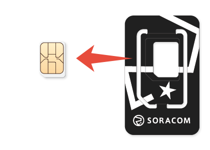
The plan01s SIM is a 3-in-1 design that allows you to conveniently break out the SIM card into standard/mini (2FF), micro (3FF), and nano (4FF) form factors. As the Spresense LTE Extension Board uses the nano (4FF) size, take care to remove the nano SIM card size when removing it from its packaging.
-
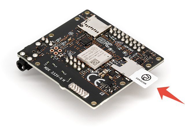
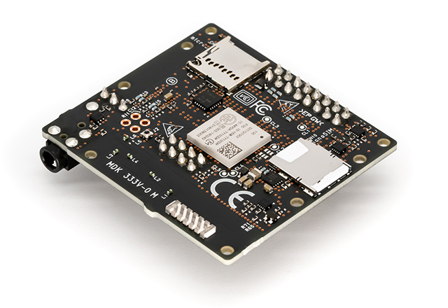
Insert the SIM card into the SIM slot located on the rear of the Spresense LTE Extension Board, paying attention to the orientation notch.
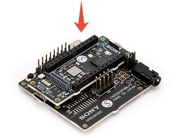
Attach the Main and Extension Boards
The Spresense Main Board and LTE Extension Board are connected using a board-to-board connector.
-
Attach the four spacers included with the LTE Extension Board.
The spacers help to ensure that the board-to-board connector is aligned correctly and to prevent damage due to uneven pressure. However, note that when using the included spacers, the main board may become difficult to remove from the extension board once attached.
If you prefer to use standoff nuts and screws (not included) to attach the main and extension boards, be aware that metallic hardware may interfere with the GNSS receiver located on the main board. Make sure to use non-metallic hardware (such as nylon) to avoid interference.
-
Attach the Spresense Main Board to the LTE Extension Board by lining up the main board with the spacers.
If any of the LTE Extension Board functions (such as LTE connection, micro SD card, or audio) do not work or seem to work improperly, the board-to-board connector may not be fitted correctly. Gently remove the main board from the extension board, then try reattaching the boards again.
If you experience issues attaching the Main and Extension Boards, refer to the Spresense Hardware documentation for additional details on attaching the LTE Extension Board.
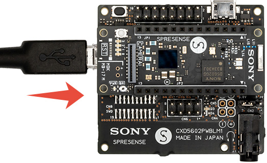
Connect the Spresense to Your Computer
In order to program the Spresense Main Board, you will need to connect it to your PC.
-
Connect a micro-USB cable to the micro-USB connector located on the Spresense Main Board.
When using the LTE Extension Board, you can use the micro-USB connector on the extension board to power your Spresense. However, in order to program the main board, you must connect the Spresense to your computer using the micro-USB connector located on the main board.
- Connect the other end of the micro-USB cable to your computer. The power LED located on the main board should turn blue to indicate that the Spresense is now turned on.
Note that during operation, the LTE module on the LTE Extension Board may consume up to 1.2A of current during cellular communication. To ensure a reliable connection, make sure to use a USB port or power supply that is capable of supplying at least 1.5A. If your USB port or power supply cannot supply sufficient current, you can connect the other micro-USB connector to another USB port or power supply. For more information, refer to the Spresense Hardware documentation.
Software Setup
Install USB Serial Drivers
When using Windows or macOS, download and install the USB serial drivers that correspond to your operating system from the following links:
- CP210x USB to serial driver for Windows 7/8/8.1
- CP210x USB to serial driver for Windows 10
- CP210x USB to serial driver for Mac OS X
When using Ubuntu Linux (64-bit), installing extra drivers is not necessary.
Install Arduino IDE
Download and install the latest version of Arduino IDE from the official Arduino Software site.
Install Spresense Board Definitions
In order for Arduino IDE to compile your code, you need to install the Arduino Spresense board definitions.
-
Start Arduino IDE.
On Windows, you may receive a security alert when you run Arduino IDE for the first time. Ensure that you enable firewall exceptions for Arduino IDE for both private and public networks.
-
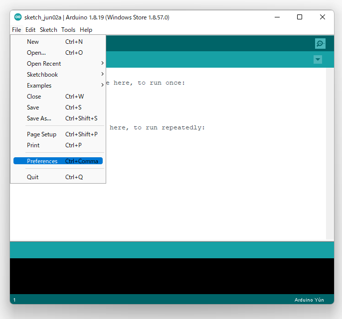
From Arduino IDE, click File Preferences.
-
Copy and paste the following URL to the Additional Boards Manager URLs field, then click OK:
https://github.com/sonydevworld/spresense-arduino-compatible/releases/download/generic/package_spresense_index.json
-
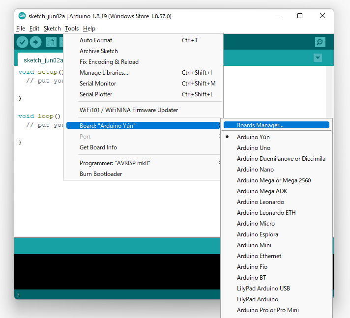
Next, from Arduino IDE, click Tools Boards Boards Manager....
-
Search for Spresense Reference Board (by Spresense Community), and click Install.

- Once the installation is complete, click Close.
Select the Spresense Board and Port
Next, let's tell Arduino IDE that our program should be compiled for our Spresense board, and select the port where our Spresense board is attached.
-
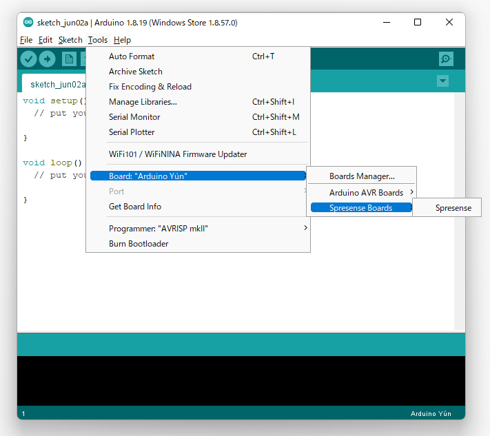
From Arduino IDE, click Tools Boards Spresense.
-
Connect the Spresense main board to your computer.
- From Arduino IDE, click Tools Port, then select the port that corresponds to your Spresense.
Install the Bootloader
Last, if you are using your Spresense board for the first time, or if you have updated to a newer version of the Spresense Arduino library, we need to install a bootloader that will allow us to program the Spresense main board.
-
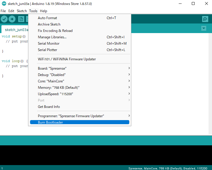
From Arduino IDE, click Tools Programmer Spresense Firmware Updater.

-
Click Tools Burn Bootloader.
-
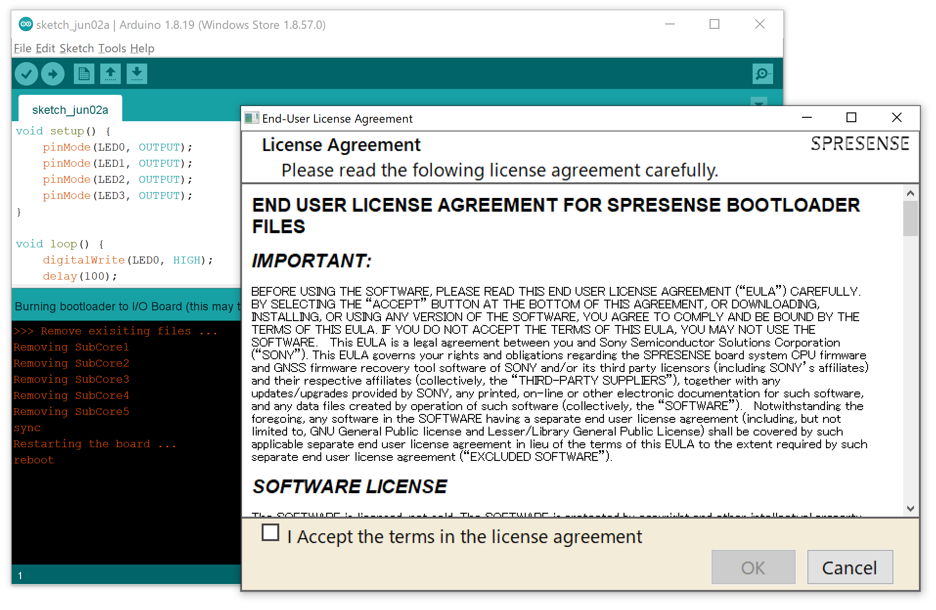
Review and accept the End User License Agreement by following the dialog.
Once the bootloader installation is done, you should see a message like this:
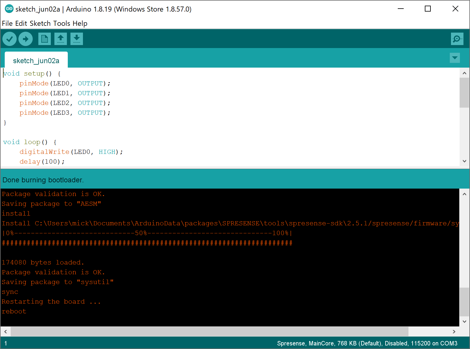
You are now ready to begin programming your Spresense main board.
If you encountered any errors, refer to the Spresense Getting Started Guide for additional details on setting up your Spresense.
Testing Your Spresense
To verify that your Spresense is set up correctly and can be programmed, we can compile and upload the following example Arduino sketch, which will simply blink the LEDs in a pattern.
-
Copy and paste the following example LED test code into a new sketch:
void setup() { pinMode(LED0, OUTPUT); pinMode(LED1, OUTPUT); pinMode(LED2, OUTPUT); pinMode(LED3, OUTPUT); } void loop() { digitalWrite(LED0, HIGH); delay(100); digitalWrite(LED1, HIGH); delay(100); digitalWrite(LED2, HIGH); delay(100); digitalWrite(LED3, HIGH); delay(1000); digitalWrite(LED0, LOW); delay(100); digitalWrite(LED1, LOW); delay(100); digitalWrite(LED2, LOW); delay(100); digitalWrite(LED3, LOW); delay(1000); } - Build and upload the LED test sketch by clicking Upload.
Once the sketch has been uploaded, your Spresense should automatically reboot and the LEDs should start blinking sequentially, confirming that your Spresense is set up correctly and has been successfully programmed.
If the LEDs do not blink, refer to the Spresense Getting Started Guide for additional details on setting up your Spresense.
Connecting to Soracom
With your Sony Spresense with LTE Extension Board set up, you are now ready to connect to a cellular network. In this section, we will enable the Soracom Harvest Data service for our Soracom IoT SIM which provides a simple way for us to collect data from our Spresense, then we will test sending some sample data.
Many services, including Harvest Data, are linked to groups. Groups let us manage multiple SIM cards together. When we enable Harvest Data for a particular group, all of the devices (SIMs) that belong to that group will automatically be able to use Harvest Data. That way we can easily add more devices to the group without having to enable Harvest Data for each SIM individually.
To set everything up, we will need to perform the following steps:
- Create a group and assign our SIM to the group
- Enable Soracom Harvest Data for the group
- Upload a new program to our Spresense, which will send sample data to Soracom Harvest Data
If you have not already done so, take a moment to follow the instructions in the SIM Registration documentation to register your Soracom IoT SIM card to your account.
Create a Group
Let’s first create a group for our SIM card.
-
If you’re not already signed in, open https://console.soracom.io again and sign in using your email address and password.
-
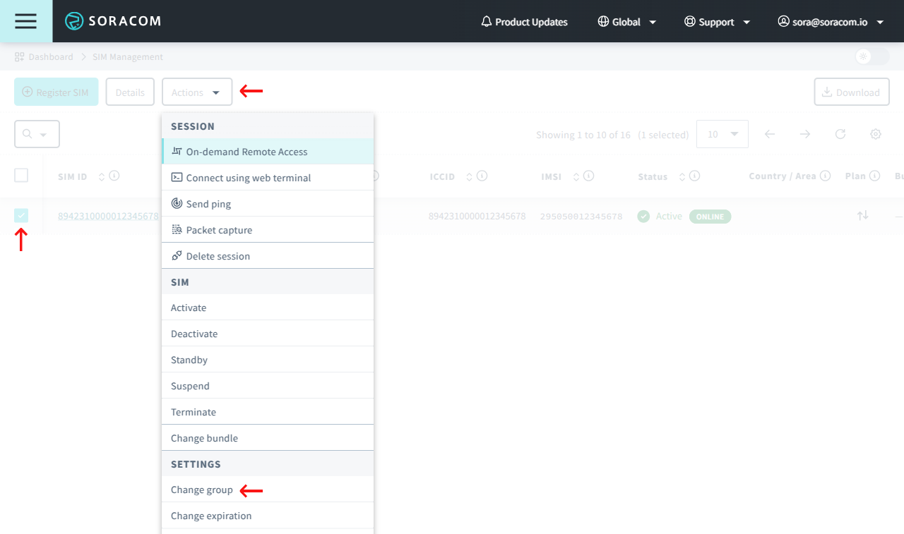
From the list of SIM cards in your account, click the checkbox next to your SIM card.
-
Then click the Actions menu, and select Change group.
-
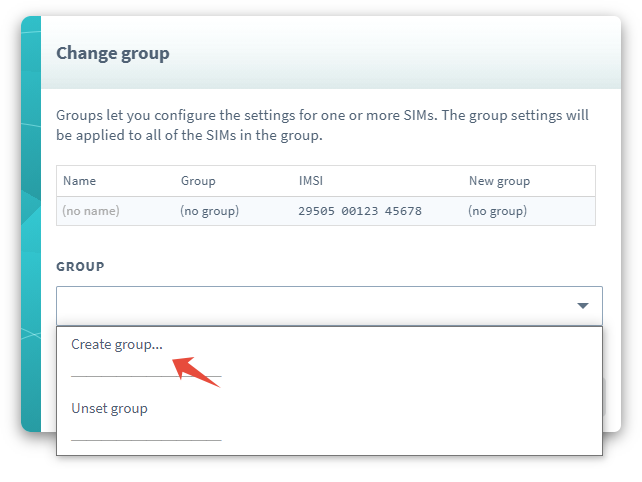
We don’t have any groups yet, so let’s create one. Click the dropdown menu, and select Create group….
-
In the popup, give the group a name, such as Harvest Group, then click Create.

-
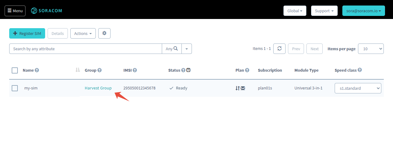
Our group has been created. Now let’s click Update to set our new group for our SIM card.

Enable Soracom Harvest Data
Next, let's enable Soracom Harvest Data for our new group.
Soracom Harvest Data is a paid service. A free tier is available which allows you to use Harvest Data for free with 1 SIM each month, which should be sufficient to allow you to test and verify that you can successfully configure your Spresense. Once you have completed setting up your device, we recommend turning off the Harvest Data service in order to avoid unwanted charges.
Note that Harvest Data provides a free tier, sending and receiving data over the cellular network will still incur data usage fees.
Refer to the Pricing & Fee Schedule for more information.
-
Click the name of the group underneath the Group column. This will open the group configuration page.
-
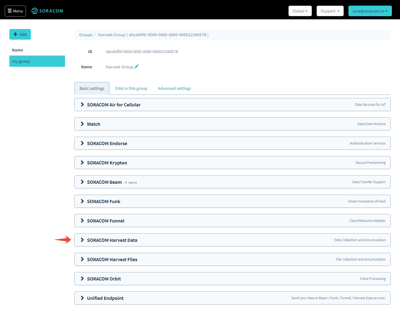
Click the Soracom Harvest Data panel to expand Harvest Data settings.
-
Click the toggle switch to turn Harvest Data ON, then click Save.
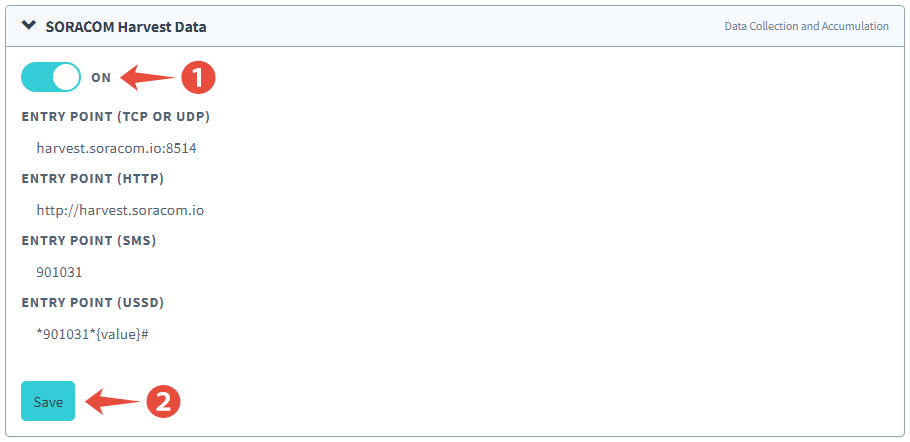
All done!
Send Test Data to Soracom Harvest Data
Now let's program our Spresense to connect to a cellular network and send some sample data to Harvest Data.
-
Copy and paste the following example code into a new sketch:
- Connect your Spresense Main Board to your computer, then click the Upload button to compile and upload the sketch to your Spresense.
Once the upload is complete, open the Serial Monitor to check the output of the program. Click Tools Serial Monitor. You should be able to see your Spresense connect to a cellular network and upload sample data. If you see a 201 response from Harvest Data, then you have successfully configured your Spresense to send sensor data to the cloud using a cellular connection!
Verify the Test Data
Finally, let's head back to the User Console to check out the test data online.
-
On the User Console, click the Menu button, and select SIM Management.
-
Click the checkbox next to your SIM card. Then click the Actions menu, and select View Harvest Data.
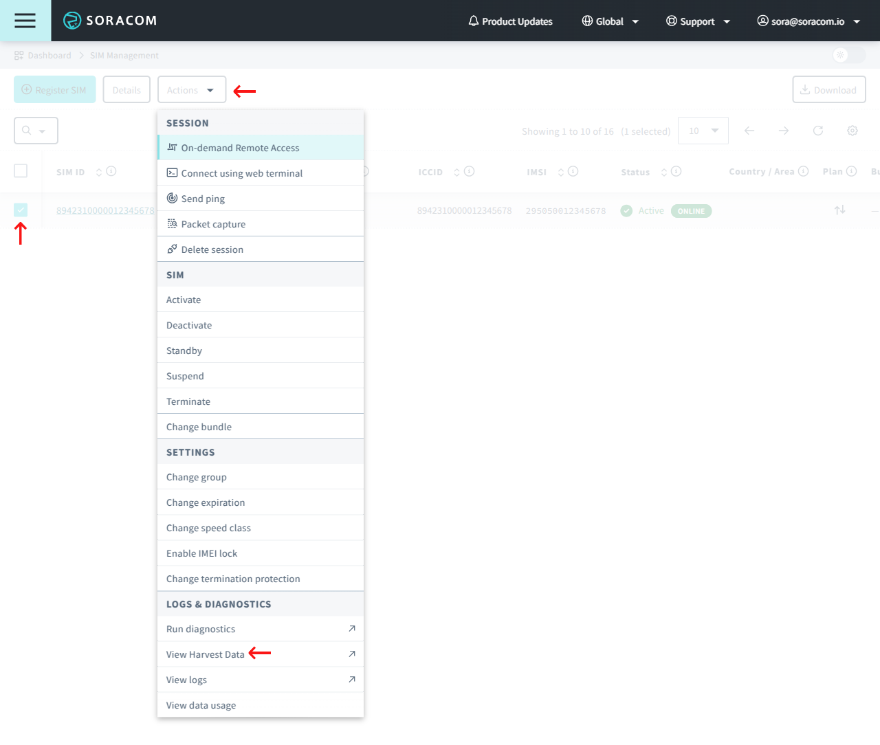
You should be able to see the Hello Soracom! test data stored in Harvest Data.
For additional information on using Harvest Data, refer to the Harvest: Configuration and Harvest: Viewing Data documentation.
Troubleshooting
If you have trouble sending data from your Spresense, the following troubleshooting steps may help you identify any potential issues. even you could successfully see the LED (green) blinked in Verify the setup part, check below for further troubleshooting.
Confirm That Your Spresense Can Be Programmed
Follow the steps in the Testing Your Spresense section to confirm that your Spresense has been set up correctly and that you are able to program it with the sample LED blinking pattern.
If you are unable to program your Spresense, you may need to retry the setup instructions steps in the Software Setup section again.
Confirm That the LTE Extension Board Is Attached Correctly
The Spresense Arduino library includes a LteTestModem sketch which you can use to check that the LTE Extension Board is attached correctly. This sketch will read the IMEI and firmware version of the LTE modem and output it to the Serial Monitor.
-
From Arduino IDE, click File Examples Examples for Spresense LTE LteTestModem to open the example sketch.
-
In Tools Port select the COM port of your Spresense.
-
Build and upload the example sketch by clicking Upload.
- Click Tools Serial Monitor and set the baud rate to 115200 baud.
You should be able to see a message similar to the following:
Starting modem test...
modem.begin() succeeded.
IMEI: 350000012345678
VERSION: RK_03_00_00_22_13151_002
RAT: LTE-M (LTE Cat-M1)
If you cannot see the message, there might be the problem in the board-to-board connection between the Spresense Main Board and the LTE Extension Board. Carefully disconnect and reattach the boards and try again.
Confirm That the Spresense Can Connect to a Cellular Network
The Spresense Arduino library also includes a LteScanNetworks sketch which attempts to connect to a cellular network and outputs cellular network connection information, including IP address, signal strength, and network carrier name, to the Serial Monitor.
-
From Arduino IDE, click File Examples Examples for Spresense LTE LteScanNetworks to open the example sketch.
-
In Tools Port select the COM port of your Spresense.
-
Build and upload the example sketch by clicking Upload.
- Click Tools Serial Monitor and set the baud rate to 115200 baud.
By default, the sketch does not include the necessary APN information and will ask you to enter it:
LTE networks scanner
This sketch doesn't have a APN information.
Enter Access Point Name:
Enter the following information in order to connect to a cellular network using your Soracom IoT SIM:
- Access Point Name -
soracom.io - Authentication type -
CHAP - Username -
sora - Password -
sora
After a few moments, if the LTE Extension Board is able to connect to a network, you should see output similar to the following:
=========== APN information ===========
Access Point Name  : soracom.io
Authentication Type: CHAP
User Name          : sora
Password           : sora
attach succeeded.
IP address: 10.123.45.67
Current carrier: SORACOM
Signal Strength: -103 [dBm]
If you see an error that your Spresense was unable to get the PIN status, check that your Soracom IoT SIM is inserted correctly. If you continue to see errors, follow the steps below to contact Soracom Support to determine if your SIM card may have been damaged.
If you do not see any output that shows the cellular network connection information, you may need to check the following:
- Follow the steps in the previous section section to ensure that the LTE Extension Board is attached correctly.
- Check the Supported Carriers page to confirm if LTE Cat-M1 (LTE-M) coverage is available in your country. Note that while Cat-M1 may be supported, some geographic areas may not yet have full coverage.
Additional Resources and Support
For complete information on Soracom User Console tools and capabilities, full documentation is available on the Soracom Developer Site.
If you run into any trouble, feel free to submit a support ticket .