Tunneling and Overlay
With Soracom Gate C2D (Cloud-to-Device), you can put the following three elements of your IoT architecture into the same virtual L2 network (Layer 2 of the OSI model; Data link layer).
- Virtual Private Gateway (VPG)
- IoT SIMs which belong to the VPG
- Gate Peer in your network
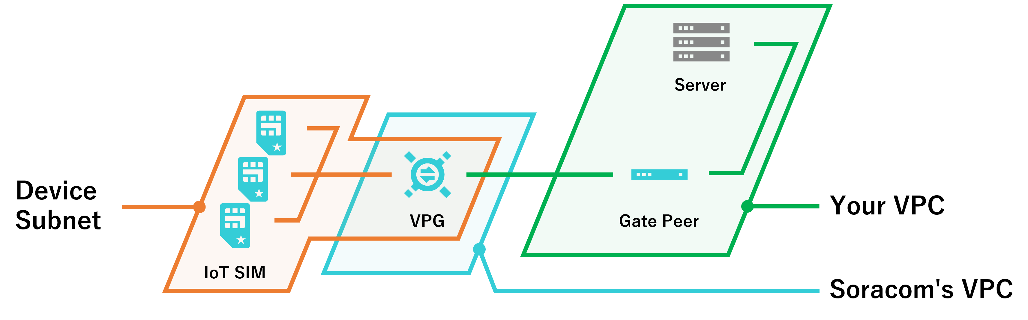
To give an overview of the tunneling technology and the overlay network used by Gate C2D, this document uses the case where your network is built on Amazon VPC (Amazon Virtual Private Cloud) and is connected to Soracom using Canal.
Before setting up Gate C2D, connect your network to the Soracom platform with the appropriate VPC, VPN, or leased line service Soracom Canal, Soracom Direct, or Soracom Door.
The Challenge of Routing Data to Your Devices
The device subnet and your network are in different L2 networks. With Canal, you can send data from the device subnet to your cloud compute via VPG, but due to NAT (Network Address Translation) at the VPG, you cannot send data from your compute back through the network to the device subnet.
Overview of Tunneling and Overlay
To put different L2 networks into the same L2 network, Gate C2D uses tunneling technology and an overlay network. Tunneling technology creates a new virtual L2 network that overlays on top of the original networks, hence it is called an Overlay network.
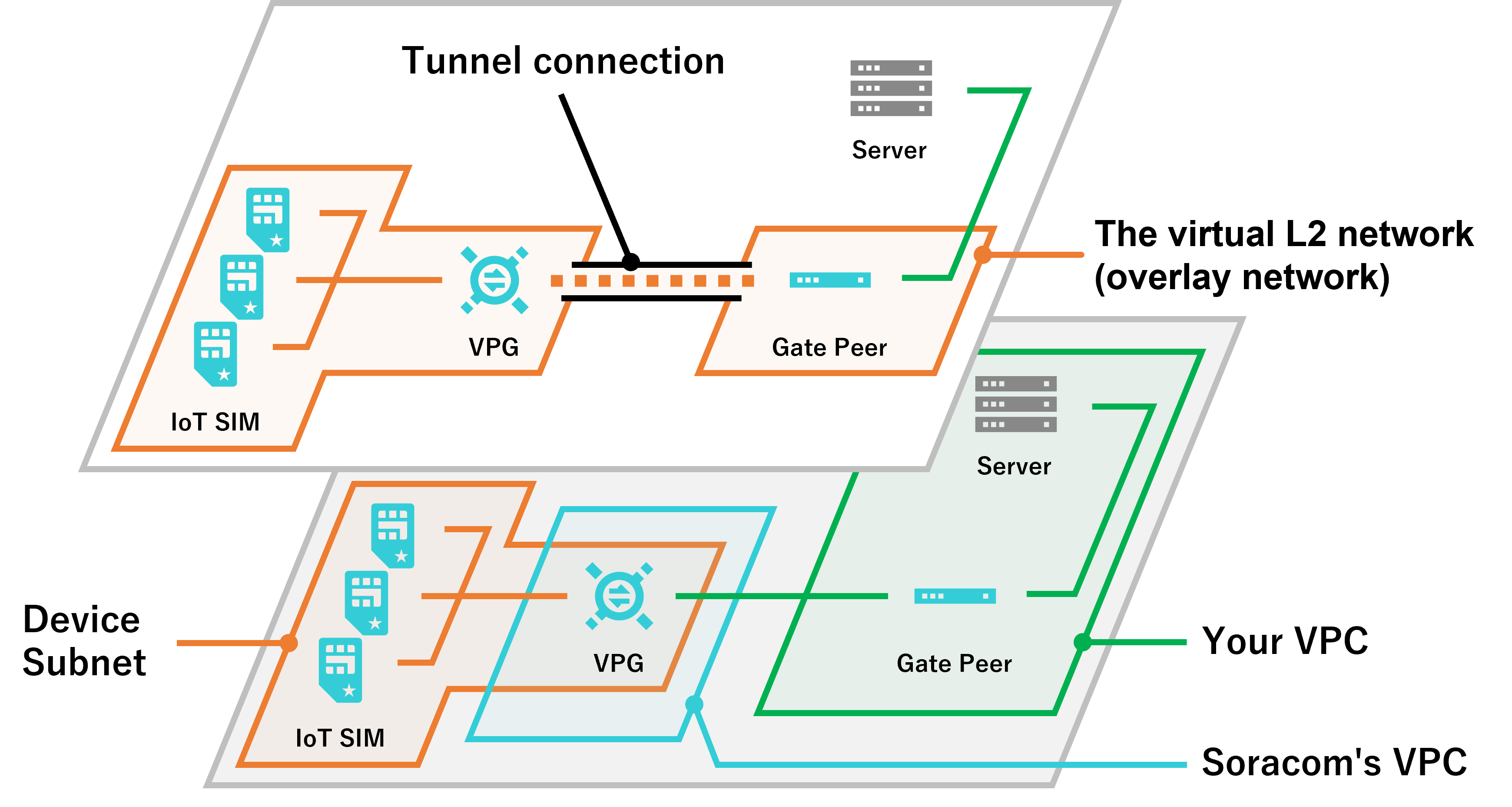
As a result of configuring the overlay network with Gate C2D, IoT SIMs and Gate Peers belonging to different networks can communicate in both directions therefore your cloud compute can now send data through the network to your IoT devices.
How to Send Data
Send Data from IoT SIM to Gate Peer
When sending data from IoT SIM to Gate Peer via VPG (e.g. When using Junction redirection), the operation is as follows.
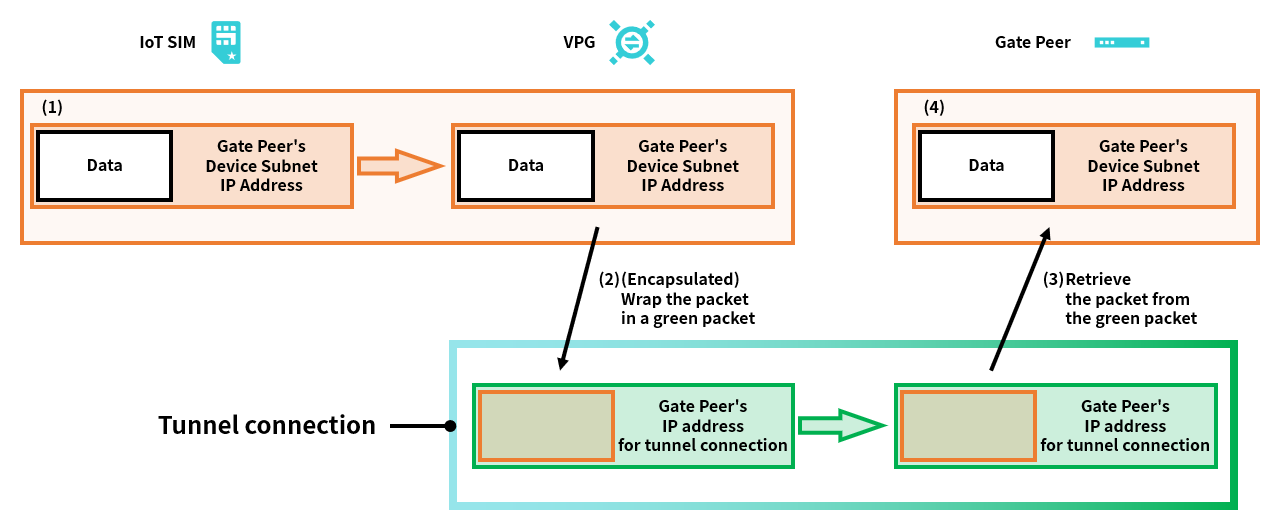
- IoT SIM sends data by specifying the “Gate Peer's Device Subnet IP Address (Inner IP Address)” as the destination.
- In VPG, packets that specify the “Gate Peer's Device Subnet IP Address” as the destination are wrapped (encapsulated) in the packets that specify the “Gate Peer's IP address for tunnel connection (Outer IP) Address” as the destination and are sent to the gate peer.
- Gate Peer de-encapsulates a packet whose destination is specified as the “Gate Peer's Device Subnet IP Address” from the (encapsulated) packet whose destination is specified as “Gate Peer's IP address for tunnel connection (Outer IP Address)”.
- Gate Peer de-encapsulates data from packets whose destination is "Gate Peer's Device Subnet IP Address".
Send Data from Gate Peer to IoT SIM
Conversely, when sending data from Gate Peer to IoT SIM via VPG, the operation is as follows.
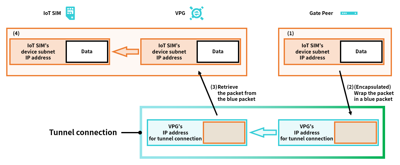
- Gate Peer creates a packet that specifies the “IoT SIM's device subnet IP address” as the destination.
- Furthermore, at the gate peer, packets that specify the “IoT SIM's Device Subnet IP Address” as the destination are wrapped (encapsulated) in the packets that specify the “VPG's IP address for tunnel connection (Outer IP Address)” as the destination and are sent to the gate peer.
- VPG de-encapsulates a packet whose destination is specified as the “IoT SIM's Device Subnet IP Address” from the (encapsulated) packet whose destination is specified as “VPG's IP address for tunnel connection (Outer IP Address)”.
- IoT SIM de-encapsulates data from a packet whose destination is specified as the “IoT SIM's device subnet IP address”.